
Two stainless steel flanges can leave the same workshop with the same grade stamp and pressure class and still behave differently in service. The flange is machined, inspected and certified; the weld that joins it to the pipe is made later, often in the field, and usually decides how long the joint lasts. That matters when you quote, because flange type, bore and bevel all change how easily the joint can be welded correctly.
This guide covers weld geometry by flange type, joint preparation, filler selection, distortion control, cleaning and what belongs on the purchase order. Final procedures and acceptance criteria must be confirmed against the applicable code, the project specification and by qualified engineering personnel.
How Each Flange Type Is Welded
The flange type decides the weld geometry, and the geometry decides what can be inspected.
| Flange type | How it joins the pipe | Weld type | Inspection access |
|---|---|---|---|
| Weld neck (WN) | Hub butt welded to the pipe end | Full-penetration butt weld | Radiography or UT possible |
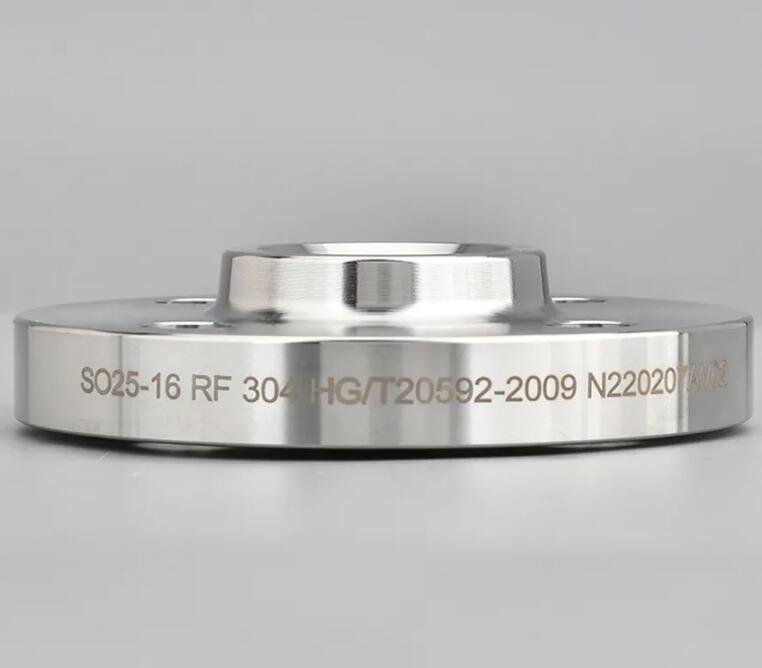
| Slip-on (SO) | Pipe through the bore, welded at the hub | Outside fillet, plus inside where required | Surface methods only |
| Socket weld (SW) | Pipe into a socket, welded at the shoulder | Single fillet, small gap at shoulder | Surface methods only |
| Lap joint (LJ) | Stub end butt welded, backing flange loose | Butt weld on the stub end only | Good on the stub weld |
| Threaded | Pipe screws into a threaded bore | No weld | Not applicable |

A weld neck carries the pipe load through a hub that tapers into the wall, so the weld joins similar thicknesses and can be fully examined. A slip-on sits outside the pipe: the pipe passes through the bore, the face is set at the correct stand-off, and fillet welds close the joint. It is quicker to align and cheaper to buy, but the joint is not full penetration. Where volumetric examination of every joint is specified, the flange type is already decided.
Joint Preparation Before the Root Pass
Bevel, bore and wall thickness
Butt welding ends are prepared to ASME B16.25, which covers welding bevels, the external and internal shaping of heavy-wall components and internal end preparation, including joints with or without backing rings, with consumable inserts and with a gas tungsten arc welding root pass. Bevel angle, root face and bore are ordered dimensions, not shop preferences.
The common problem on stainless orders is a bore that does not match the pipe wall. A weld neck ordered for Schedule 40S is bored for that wall; if Schedule 80S pipe arrives, the joint becomes a thickness transition needing machining or an approved detail. State the schedule, or the measured wall thickness, with the enquiry.
Fit-up and alignment
Internal misalignment at the root survives longest, because it concentrates stress where no external inspection reaches. Align the bore, not the outside diameter, and check before tacking. Tacks should use the production filler and be fused into the root pass. On socket welds, do not bottom the pipe in the socket: piping codes require a small gap to the shoulder so contraction does not crack the joint as it cools.
Cleanliness and tool control
Stainless steel loses corrosion resistance where iron is embedded, so keep brushes, discs and clamps used on carbon steel away from it, and remove grease and ink from the bevel before welding.
Filler Metal Selection
Filler is chosen to match the parent metal and the service, and the two are not always the same. A 316L flange welded with 308L filler passes a visual inspection, but the deposit is lower in molybdenum and corrodes first in chloride service.
| Parent material | Filler commonly specified | Note |
|---|---|---|
| 304 / 304L | ER308L | Low-carbon deposit |
| 316 / 316L | ER316L | Molybdenum-bearing deposit |
| 321 / 347 | ER347 | Niobium-stabilised deposit |
| 2205 duplex | ER2209 | Balanced ferrite-austenite deposit |
| 2507 super duplex | ER2594 or nickel-alloy filler | Governed by the procedure |
| 904L | ER385 | High-molybdenum austenitic deposit |
| Stainless to carbon steel | ER309L or nickel-alloy filler | Dilution control governs |
The L suffix matters: a 316L flange should normally receive a low-carbon 316L deposit. Austenitic weld metal is also usually controlled to roughly 3 to 10 FN of ferrite to reduce solidification cracking, which is why filler and procedure are approved together rather than separately.
Shielding gas and backing purge
Austenitic and duplex grades use argon-based shielding, and the root of an open butt weld is normally purged with argon. Without a purge the root oxidises, loses corrosion resistance and forms scale that is hard to remove later. The purge is checked with an oxygen meter, and the finished root is judged by heat tint: silver or straw is generally acceptable, heavy blue, purple or black oxide is a defect.
Heat Input, Interpass Temperature and Distortion
Austenitic stainless steel conducts heat at roughly a third of the rate of carbon steel and expands more when heated. Heat stays close to the arc, surrounding metal restrains expansion, and contraction pulls the face out of flat, so a flange that was flat at goods-inward inspection ends up dished or tapered after welding.
Control is procedural: low heat input, stringer beads rather than wide weaving, a capped interpass temperature (many specifications use around 150 °C) and cooling time between passes. Duplex grades need a window rather than a simple maximum, because too little heat input leaves an unbalanced microstructure and too much promotes harmful intermetallic phases.
Balance shrinkage: weld opposite segments, back-step long seams, fixture thin or large flanges, and leave machining stock on faces that will be finished after welding. Never quench a stainless weld: rapid cooling raises residual stress and can alter the microstructure the procedure was written to produce.
Cleaning After Welding
Welding leaves heat tint, oxide scale and embedded iron, all of which shorten service life. Heat tint is a chromium-depleted oxide with little corrosion resistance and a common starting point for pitting. Pickling removes it; passivation restores the passive film on a clean surface. ASTM A380/A380M covers cleaning, descaling, pickling and passivation of stainless steel parts, and describes the free-iron and water-break checks used to judge cleanliness; passivation acceptance is addressed in ASTM A967/A967M.
In practice: remove spatter, clean the weld and heat-affected zone, pickle where tint is present, passivate, rinse and dry, using abrasives that have never touched carbon steel.

Inspection After Welding
The flange standard and the weld acceptance criteria are different documents. ASME B16.5 covers the pressure-temperature ratings, materials, dimensions, tolerances, marking and testing of the flange as a component, and is limited to cast or forged flanges, with blind and certain reducing flanges also permitted from plate. It does not say whether a weld is acceptable; that comes from the piping or vessel code and the project specification.
A typical package includes visual examination of the weld, tint and spatter; penetrant testing of fillets where specified; radiography or ultrasonic testing of butt welds at the stated extent; ferrite checks on duplex welds; positive material identification where required; and pressure testing to the pressure set by the design authority. A certificate to EN 10204 3.1 confirms the flange, not the weld.
What to Put on the Purchase Order
- Flange type, size and pressure class, with the governing standard and edition.
- Material specification and grade, for example ASTM A182/A182M F316L, plus any supplementary requirement.
- Bore matched to the pipe schedule, or the measured wall thickness on non-standard lines.
- Bevel preparation referenced to ASME B16.25, and whether an open root, backing ring or consumable insert is expected.
- Facing and finish, plus the facing of the component the flange will bolt to.
- Whether the welding procedure and filler need approval, and the extent of examination.
- Certificates, marking, surface protection and packing.
Frequently Asked Questions
Can a slip-on flange weld be radiographed?
Not in any useful sense. Slip-on flanges are joined by fillet welds, and radiography is intended for full-penetration butt welds. These joints are assessed by visual and surface examination. If volumetric examination of every joint is required, specify weld neck flanges.
Which filler metal should be used for a 316L flange?
ER316L is the usual matching choice, because it keeps the molybdenum content and low carbon level of the flange. For a dissimilar joint, such as a 316L flange to carbon steel pipe, a higher-alloy filler such as ER309L or a nickel-alloy filler is normally selected to control dilution. The final choice belongs to the qualified procedure.
Does stainless steel need preheating, or heat treatment after welding?
Neither, for austenitic grades. Preheating is used on carbon and low-alloy steels to avoid hydrogen cracking, which is not the mechanism at work here, and stress relief by heat treatment is impractical for most field joints. Duplex and some high-alloy grades have their own requirements, and any heat treatment must be specified by the design authority rather than added on site.
Why does the flange face go out of flat after welding?
Localised heat input combined with restraint causes uneven contraction, and thin or large-diameter flanges distort most. Prevention is procedural: low heat input, balanced sequence, controlled interpass temperature and adequate fixturing. Where flatness is critical, leave machining stock and finish the face after welding.
Conclusion
The flange is the part of the joint that arrives with a certificate; the weld decides whether the joint holds. Getting it right starts before the purchase order: the type sets the weld geometry, the bore has to match the pipe, the bevel has to suit the procedure, and the filler has to match the grade. Heat input keeps the face flat, cleaning keeps the corrosion resistance in the metal rather than in the mill certificate, and inspection has to match the weld type that was actually ordered.
Use this guide to ask better questions, then confirm the answers against the governing code, the project specification and your welding engineer: the acceptable procedure depends on the design conditions of the line.
If you are specifying stainless flanges for a welded line, send the size, class, material grade, pipe schedule and facing through our contact page and we will quote against those parameters. Our weld neck flange range covers butt-welded connections, and the slip-on flange range covers the fillet-welded alternative.
Reference
ASME. B16.25 – Buttwelding Ends. Official standard page, accessed 2026.
ASME. B16.5 – Pipe Flanges and Flanged Fittings, NPS 1/2 through NPS 24. Official standard page, accessed 2026.
ASTM International. A380/A380M – Cleaning, Descaling, Pickling and Passivation of Stainless Steel Parts. Official standard page, accessed 2026.