
A reducing flange solves a specific geometry problem: the connection on one side is sized for a larger pipe, while the line behind it is smaller. Instead of adding a reducer and a second flange, the transition is machined into the flange itself. Outside diameter, thickness and bolt pattern follow the larger size, so the joint mates with standard equipment; bore and hub follow the smaller pipe, so the weld end, socket or thread matches the line.
It is a small part with a disproportionate number of ways to be ordered wrongly, because one short description can hide two nominal sizes, two schedules and a hub length that no table fixes. This guide covers the types, what the standards tabulate, the values that define the part and the checks to make before ordering. It is general technical information; acceptance criteria come from the applicable standard edition, the project specification and a qualified engineer.
What a Reducing Flange Actually Is
A reducing flange is one component carrying two sizes. The body – outside diameter, thickness, bolt circle, hole count, hole diameter and facing – belongs to the larger nominal size and its class. The bore, and on a weld neck the hub, belong to the smaller pipe. The part is written with the larger size first: NPS 6 x 4, Class 150, raised face, weld neck, ASTM A182 F316L.
The class belongs to the body. A 6 x 4 Class 150 reducing flange is a Class 150 flange; the reduced bore neither lowers the rating nor upgrades the line it bolts to. It changes the connection size at the back of the flange and the shape of the flow path through it.

The Types You Will Be Quoted
Reducing weld neck flange
The hub is machined for the smaller pipe and butt welded to it, while the ring keeps the larger bolt pattern. It is the usual choice for higher pressure, cyclic duty and critical welds, because the hub moves the weld away from the ring and contains the transition in a smooth contour. Hub and overall length are therefore calculated from the two sizes, not read from a table.
Reducing slip-on flange
Two fillet welds on a body sized to the larger flange. It is cheaper and easier to align than a weld neck, but fatigue performance is lower and the bore step is abrupt at the face.
Reducing threaded flange
The only reducing configuration ASME B16.5 tabulates directly, which makes it the easiest to specify and to audit. It suits small utility and instrument lines where welding is unwanted; thread engagement and sealant practice matter more than the body.
Reducing plate flange
A plate or bore-cut flange with the larger outline and a smaller bore, usually hubless. Common in lower-pressure water and utility service and in drawing-controlled EN-style work where plate thickness is set by the project.
| Type | Smaller bore made by | Where it fits | Fix in writing |
|---|---|---|---|
| Reducing weld neck | Hub and bore machined to the small pipe | Higher pressure, cyclic duty | Overall length, bore, weld prep |
| Reducing slip-on | Bore and hub sized to the small pipe | Lower pressure, utility | Bore, hub diameter, weld detail |
| Reducing threaded | Taper thread to the small size, tabulated | Small utility and instrument lines | Thread type, class, facing |
| Reducing plate | Plate bored to the small size | Low pressure, drawing-controlled | Plate thickness, bore, facing |
Reducing Flange or Reducer
Both connect two sizes, so the decision is about space, weld count and flow, not about which is correct in principle.
| Factor | Reducing flange | Flange with reducer |
|---|---|---|
| Length | No added run length | Adds reducer length |
| Parts and welds | One part, one butt weld | Two parts, two or three welds |
| Bore transition | Short, relatively abrupt | Longer, smoother |
| Size step | Typically one or two sizes | Any covered reduction |
| Erosion risk | Higher, close to the joint | Lower, spread over length |
The limit is the size step. A one- or two-step reduction is routine; a 10 x 3 in one flange concentrates the contraction at the face and produces a bore geometry no standard describes. Where the reduction is large, the fluid abrasive or the velocity high, a reducer keeps erosion away from a boundary that also has to seal.
What the Standards Do and Do Not Tabulate
ASME B16.5 covers flanges from NPS 1/2 to NPS 24 in Classes 150 through 2500, including ratings, materials, dimensions, tolerances, marking and testing. It recognises reducing flanges and fixes the size designation – larger size first, then the smaller bore, as in “NPS 6 x 2 1/2 Class 300 reducing threaded flange”. Reducing threaded flanges are tabulated, which makes that version easiest to audit.
Reducing weld neck and slip-on flanges are not tabulated as a separate family. They apply the body dimensions of the larger size to a hub and bore sized for the smaller pipe, with hub or overall length calculated. That distinction is commercial as well as technical: two suppliers can both quote “6 x 4 Class 150 WN” and deliver different lengths, each internally consistent. Put the dimension on the drawing. Above NPS 24, ASME B16.47 governs large-diameter flanges, but reducing versions there are drawing-made parts.
EN 1092-1 works differently: it lists types by geometry and facing and has no reducing type, so a reduced-bore PN flange is normally drawing-controlled. An ASME reducing flange should not be translated into “PN 16, DN 100/80” and expected to be equivalent, because body, facing and bolting are dimensioned independently. See the ASME B16.5 standard description for scope.
Six Values That Define the Part
- Larger size and class: the equipment or valve size, which owns the pattern, outside diameter and thickness.
- Smaller size and wall: the bore follows pipe inside diameter, so 4 in Schedule 40 and Schedule 80 are different parts. See flange bore and pipe schedule.
- Facing: raised face, flat face or ring type joint, with finish if the gasket is critical; for RTJ, groove type and ring number.
- Hub or overall length: calculated on reducing weld necks. Agree it, or accept what the workshop calculates.
- Grade and product specification: for example ASTM A182 F316L forgings, or ASTM A240 plate. Grade and product form are separate statements.
- Gasket and bolting: gasket outside diameter follows the larger facing, inside diameter must clear the smaller bore, studs fit the larger pattern.
Stainless Grades That Make Sense
Grade selection belongs to the fluid, chloride level, temperature and governing code. As general guidance, 304 and 304L cover benign process service; 316 and 316L add molybdenum for moderate chlorides; 321 and 347 are stabilised for elevated temperature; duplex 2205 and super duplex 2507 add strength and chloride stress corrosion resistance; 6% molybdenum grades and nickel alloys suit severe chloride and seawater duty.
Reducing flanges are commonly forged to ASTM A182 in grades such as F304, F304L, F316, F316L, F44, F51 and F53, or machined from ASTM A240 plate. Product form matters: a plate flange is not a forging, and a certificate should name the specification, grade and heat number rather than “stainless steel”. Where required, positive material identification and a 3.1 certificate confirm the delivered part.
Common Ordering Errors
- Quoting the smaller bolt pattern. The part then cannot bolt to its own equipment; the pattern follows the larger end.
- Naming the smaller size without the schedule. The bore becomes whatever the supplier assumed, and the weld prep no longer matches the pipe.
- Reusing a gasket from the small line. It leaves part of the larger facing uncovered and can sit over the bore edge.
- Assuming a hub length. Nothing fixes the overall length of a reducing weld neck, so a fixed spool dimension must be stated.
- Mixing rating systems. Class 150 does not mate with PN 16, and JIS 10K is a third geometry.
Inspection and Documentation
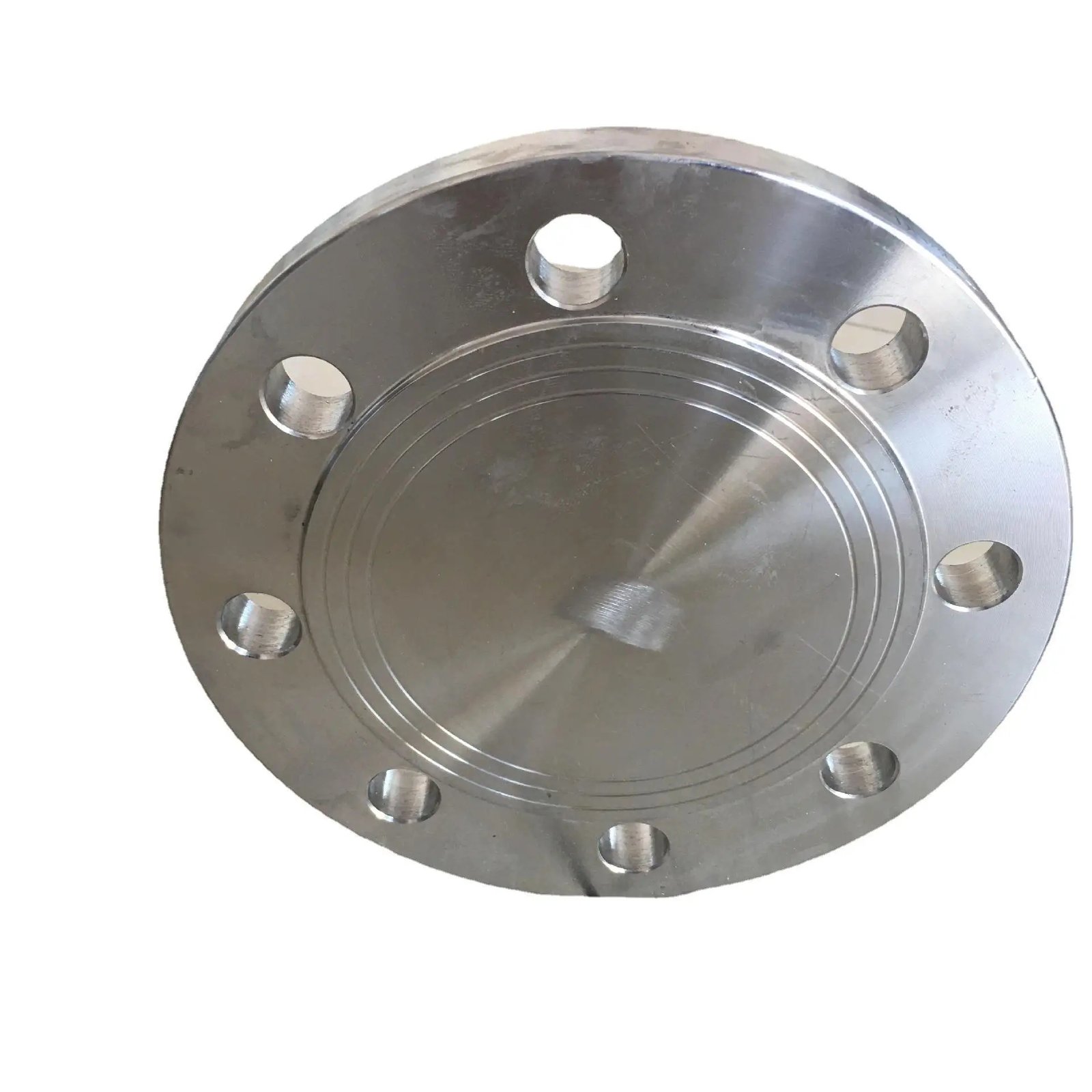
Check the part like any flange, plus two values: measure the bore against the pipe it will receive, and the pattern against the part it will bolt to. Confirm overall length if specified, and confirm the rim marking – size, class, facing, grade and manufacturer identification. Documentation follows the purchase order: dimensional report, material certificate with heat number, PMI where requested, and any examination or pressure test the specification calls for – pressure testing is not implied by a flange description.
Frequently Asked Questions
Can a reducing flange replace a reducer?
For a one- or two-size reduction, yes. For large reductions, abrasive service or high velocity, a pipe reducer is usually better; that is a design decision, not a purchasing one.
How should the size be written on an inquiry?
Larger size first, then smaller size, class, facing, type and material specification – for example “NPS 6 x 4, Class 150, RF, reducing weld neck, ASTM A182 F316L, bore to Schedule 40S”. Add the overall length if the spool has a fixed dimension.
Does the smaller bore reduce the pressure rating?
The body is rated as the larger size in its class for the material group. The bore does not create a different class, but the assembly is still limited by pipe, gasket, bolting and mating flange.
Which gasket size is correct?
The one matching the larger facing, because that is the sealing surface, with an inside diameter that clears the smaller bore. A gasket sized for the small line will not seal against the large raised face.
Can a reducing flange be used on a pump suction?
It can, but the layout needs review. Suction lines usually need a straight run and, on horizontal runs, a flat-bottom eccentric transition to avoid air pockets. A concentric reduction at the face is not equivalent to the eccentric reducer the pump was selected around.
Conclusion
A reducing flange is a compact answer to a common mismatch, and most of the risk sits in the description rather than the machining. State the larger size and class that own the pattern, the smaller size and schedule that own the bore, the facing, the overall length if it matters, and the material specification. Separate what the standard tabulates from what the workshop calculates, and the part will fit the first time.
If you are specifying one, send the larger size and class, the smaller size and schedule, the facing, the material specification and the documentation you need. Our team will confirm bore, pattern and drawing before anything is machined. Send your reducing flange requirements, or review the weld neck flange and slip-on flange ranges the reducing versions are based on.