
An orifice flange is a pipe flange that carries the pressure tappings for a differential-pressure flow meter. Two flanges face each other across an orifice plate, each tapped so that a transmitter reads pressure upstream and downstream of the plate; the difference becomes flow. Everything else – outside diameter, thickness, bolt circle, facing – is ordinary flange geometry from the base standard.
That combination is why orifice flanges are ordered wrongly more often than plain flanges. A buyer specifies “6 inch, Class 300, stainless”, receives a dimensionally correct flange, and later finds the tappings pointing the wrong way, the jack screw holes missing, or the mating flange drilled as a mirror image. This guide covers what the standard tabulates, what it leaves to the purchase order, and the checks worth making before assembly. It is general technical information: acceptance criteria come from the applicable standard edition, the project specification and a qualified engineer.

What Makes a Flange an Orifice Flange
Pressure tappings. Each flange carries a hole from the outside diameter through to the bore, terminating at the face. One flange senses upstream pressure, the other downstream. Tap position – distance from the plate, angle in plan, thread – is the detail most often missing from an enquiry.
Jack screw holes. Tapped holes separate from the bolt holes, accepting jack screws. When the joint must be opened to change the plate, the screws are driven against the mating flange to spread the pair apart without levering on the faces or cutting the pipe.
Pairing. Two flanges are machined and drilled as a set so the tappings align with each other and with the pipe axis, and each jack screw hole lands on solid metal rather than on a bolt hole.
What ASME B16.36 Covers, and What It Leaves to You
The governing standard is ASME B16.36, Orifice Flanges, currently the 2025 edition. Its published scope is narrow: flanges with orifice pressure differential connections, otherwise similar to those in ASME B16.5, limited to welding neck orifice flanges in Classes 300, 400, 600, 900, 1500 and 2500, plus slip-on and threaded orifice flanges in Class 300.
Two consequences follow. The class range is not continuous across body types – a Class 600 slip-on orifice flange is not a catalogued B16.36 item and becomes an engineered part agreed in writing. And Class 150 orifice flanges sit outside that scope as published; they are commonly produced from B16.5 dimensions with tappings added to the purchaser’s drawing, which works provided the drawing says so.
Much else stays outside the standard: the plate, plate seal, tap piping, manifold, transmitter and the straight-run lengths either side of the meter. Those belong to ISO 5167-2, the meter vendor and the piping designer. A flange that meets B16.36 is a compliant component, not a commissioned flow meter.
Tap Arrangements and What They Change
The three recognised arrangements are not interchangeable: each fixes the tapping point at a different distance from the plate, and so yields a different discharge coefficient.
| Tap arrangement | Where the tappings sit and what it implies |
|---|---|
| Corner taps | Open at the corner formed by plate and pipe wall. Compact, common on smaller lines, least tolerant of an off-centre plate. |
| Flange taps | Each tapping set a fixed distance from the plate face – conventionally one inch – drilled through the flange. This is what most orifice flanges are bought for. |
| D and D/2 taps | Upstream one pipe diameter, downstream half a diameter. They usually sit on the pipe or a carrier, so the flange stays plain and the taps fall outside its scope. |
ISO 5167-2:2022 covers plates used with flange, corner or D and D/2 tappings, requires subsonic single-phase flow, and excludes pipe sizes below 50 mm or above 1,000 mm and Reynolds numbers below 5,000. A project outside those limits is being designed by another route, and the drawing should say which.
Writing the Specification So the Part Can Be Made
Most of the cost of a wrong orifice flange is the delay and re-machining, not the part.
| Specification item | What the drawing or purchase order must state |
|---|---|
| Size and class | Nominal size, pressure class and standard edition – B16.36 with the year. |
| Body type | Welding neck, slip-on or threaded, with weld end preparation or thread form; confirm it is inside the standard’s scope. |
| Facing | Raised face or ring joint, with facing height, groove type and finish. |
| Tap details | Arrangement, thread size and form, angular position relative to the bolt holes, and how the partner flange is machined. |
| Jack screws | Number and thread size, and whether supplied loose, fitted or omitted. |
| Plate interface | Plate bore, thickness and diameter ratio, and whether plate, gaskets and seals are in scope. |
| Material | Forging grade, for example an ASTM A182 F316L forging, with the certificate named. |
| Inspection | Dimensional report, tap position check, face finish, NDE and any third-party witness point. If it is not named, it will not happen. |
Jack Screws: Small Parts with a Real Job
Jack screw holes are often the first item to disappear when a purchase order is abbreviated, because they add machining and do not affect the pressure boundary. Their absence is felt during a shutdown, with the line drained and the plate due for replacement, when the only way to open the joint without damaging the faces is to drive the screws.
The threads should be cut in the flange that carries them, not improvised on site with a hand drill, and the screws should stay with the assembly, lightly lubricated and protected. Treat them as separation tools, not alignment tools: pulling a misaligned joint into place with them loads the faces in a way they were never designed for.
Installation Details That Decide Whether the Meter Works
Straight run and flow condition
ISO 5167-2 sets the straight lengths needed for an acceptable velocity profile, and the requirement changes with the fitting immediately upstream – a single bend, a double bend in plane, a valve or a reducer each carry a different penalty. The flange drawing does not fix this; the piping layout does.
Concentricity and plate orientation
The plate bore must be concentric with the pipe bore and the plate square in the joint. A plate installed with its bevelled edge facing downstream is a classic commissioning fault, and it is invisible once the joint is closed.
Tap lines and trapping
Tap lines must slope so gas does not collect in liquid service and condensate does not collect in gas service. Long, uninsulated tap lines are a common source of drift that gets blamed on the flange.
Materials and Facing Choices for Stainless Orifice Flanges
For stainless service the body is normally a forged austenitic grade: 304L for general duty, 316L where chlorides or a wider chemical envelope are involved, and stabilised grades such as 321 or 347 for elevated temperature or weld sensitisation. Duplex and super duplex forgings suit chloride stress corrosion cracking and higher strength; 6Mo grades suit pitting resistance in seawater. A105 carbon steel remains the default for non-corrosive utility meters.
Facing follows the duty rather than the material. A raised face with a serrated or smooth finish and a spiral wound gasket covers most meter stations. Ring joint facing suits high pressure classes, cyclic or high-temperature service and projects that demand a metal-to-metal seal – and it must be specified with the groove type, because groove and gasket ring are a matched pair.
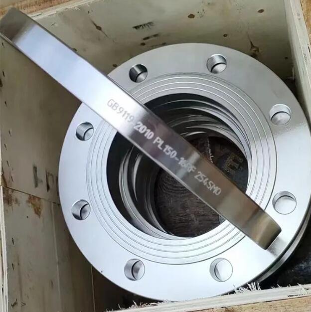
What to Check When a Pair Arrives
Incoming inspection is mostly a matter of looking at the features a standard flange does not have. Beyond the marking, certificate, grade and face finish checks in our stainless steel flange inspection guide, four items deserve their own line on the report.
- Tap position. Measure from face to tapping centreline, check the angle against the drawing, and confirm the hole is clear to the bore with no burr or swarf.
- Tap thread. Confirm form and size with a gauge, and that it matches the fittings the instrument contractor is supplying.
- Jack screw holes. Confirm they exist, the thread is clean, and each lands on solid metal in the mating flange.
- Pair match. Offer the two together, check the tappings align as drawn, and confirm the pair is marked and packed as a set.
Frequently Asked Questions
Are orifice flanges always supplied in pairs?
They are used in pairs and should be ordered and marked as a pair. A single spare bought for stock only becomes useful when matched to its partner.
Can a standard weld neck flange be converted into an orifice flange?
It can be drilled and tapped, and in maintenance that is sometimes the pragmatic answer. It is not the same as buying a B16.36 flange: tap positions, jack screw holes, marking and documentation all have to be engineered and inspected.
Does the flange come with the orifice plate?
Normally not. The plate, its bore calculation, material and edge condition belong to the meter supplier or process designer. If the plate is expected in the flange scope, state bore, thickness, material and edge profile.
Raised face or ring joint?
Raised face is the default for general service and is easier to break and remake. Ring joint suits metal-seal duty at high pressure, high temperature or cyclic service, and brings a matched groove and gasket pair with tighter finish control.
Ordering an Orifice Flange Pair Without the Rework
The part is not complicated: a standard body, two tappings, jack screw holes and a facing. The difficulty is that each addition is defined by the purchase order rather than the catalogue, so an enquiry that stops at “stainless orifice flange, 6 inch, Class 300” leaves the supplier to guess. State the standard and edition, body type, facing, tap arrangement and position, jack screws, material and certificate, and whether the plate is in scope – then ask for the dimensional record with the delivery, so the pair is checked on arrival rather than on the day of the shutdown.
If you are specifying orifice flanges for a meter station, our team can review the drawing against the applicable standard and quote the pair with taps, jack screws and documentation called out. Send the line size, class, facing, tap arrangement and material through the contact page. Bodies come from our weld neck flange and pipe flange ranges, with tapping and jack screw details added to your drawing.
Technical information in this article is general. Final selection, pressure rating and acceptance criteria must be confirmed against the applicable standard edition, the project specification and by a qualified engineer.