
A flange that will not bolt to its partner is rarely a mystery. A bolt pattern is a set of fixed dimensions: bolt circle diameter, hole count, hole diameter, hole position and facing. When two flanges disagree on any one of them, no amount of lubricant or extra force will make the joint reliable.
Most mismatches are created before the crate is opened: a class quoted against a PN, a large-diameter series chosen by habit, a drawing revised without the mating part, or an inquiry that named the size but not the standard. This guide covers the pattern, the common mismatches, how to measure before ordering, and what to write on the purchase order. It is general technical information; acceptance criteria come from the applicable standard edition, the project specification and a qualified engineer.
What a Flange Bolt Pattern Actually Defines
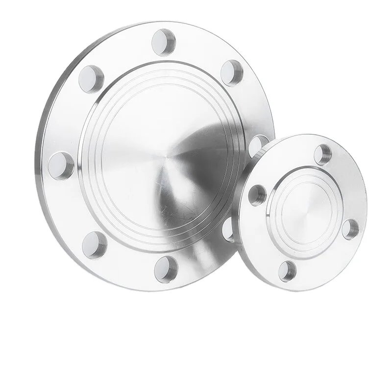
A bolt pattern is not one dimension but a group that only works together:
- Bolt circle diameter (BCD): the circle on which hole centres sit; it decides whether two flanges can be drawn together.
- Hole count: four, eight, twelve or more. The same bolt circle with a different count will not assemble.
- Hole diameter: a clearance hole for the stud, not a locating fit, which is why a joint can start to assemble and then stop.
- Hole position and facing: angular spacing and index, plus RF, FF or RTJ facing, which changes the gasket and stack height.
- Bolting: stud diameter, thread and grade. They must pass the holes and carry the design load.
The dimensional standard fixes this geometry: ASME B16.5-2025 covers NPS 1/2 to 24 in Classes 150 to 2500, and B16.47-2025 covers NPS 26 to 60 in Classes 75 to 900. A flange is defined by size, class, standard and facing together, never by size alone.

Why Bolt Holes Fail to Line Up
Class and PN are different rating systems
The most common export mismatch is a Class 150 flange quoted against a PN 16 line, or the reverse: both are called “about 150” and neither fits the other. ASME classes and EN PN ratings are separate systems with different thicknesses, bolt circles, bolt sizes and facing dimensions; a gasket that suits one will not correct the other. JIS B2220 is a third system, so a 10K flange should not be assumed to mate with ASME Class 150.
Large-diameter flanges have two series
Above NPS 24, ASME B16.47 contains Series A and Series B, dimensioned differently for the same nominal size and class, including bolt circles and hole counts. Both are legitimate; they are not the same part. A quotation for “B16.47, NPS 30, Class 150” that omits the series is incomplete.
Size and type variants shift the pattern
Reducing flanges, spectacle blinds, orifice flanges and adapter spools can carry a pattern that follows a different nominal size. A reducing flange is normally dimensioned to its larger end.
“Same as last time” and drawing drift
Repeat orders are where documentation quietly diverges. A drawing is revised, the supplier machines to the latest file, and the mating flange in the yard is still to the previous revision. The order says “as before”, the workshop says “latest drawing”, and both are internally consistent and externally incompatible.
Simple faults produce the same result: a hole drilled off the index, a bolt circle machined to the wrong table, a peened hole edge, or a wrong size marking. Goods-in checks should measure the pattern, not trust the marking.
How to Measure a Bolt Pattern Before You Order
Measure the part that already exists, not only the part you are buying. The mating flange, valve or nozzle is the fixed reference. Record every value with its unit, size and class.
| What to establish | How to verify it |
|---|---|
| Nominal size and class or PN | Read the rim marking; compare with the line list, not the pipe diameter. |
| Standard and series | Take standard, edition and, for B16.47, the series from the drawing or certificate. |
| Bolt circle diameter | Even hole count: measure centre to centre across opposite holes. Odd count: measure to the flange centre and double it. |
| Hole count and spacing | Count every hole and confirm even spacing; one misplaced hole is easy to miss. |
| Hole diameter | Caliper or internal gauge in two directions; compare with stud diameter and standard table. |
| Hole index and facing | Note the pattern relative to the top centreline; confirm RF, FF or RTJ. |
| Bolting and stack height | Confirm stud diameter, thread, grade and length for both flanges, gasket and nuts. |
Do not convert an inch pattern to a rounded metric value and order from that number. Measure more than one hole pair: a dropped flange can have a correct average bolt circle and one hole out of position.

Why “It Almost Fits” Is a Warning
Because the holes are clearance holes, two flanges can be close enough for two or three studs to pass while the rest refuse. That partial assembly is more dangerous than a clear mismatch, because it invites force. Pulling the flanges together with drifts, reaming a hole or using oversized studs distorts the flanges, compresses the gasket unevenly, and never reaches the preload the design assumed.
On a pressure boundary, a hole is not a field adjustment. Enlarging or slotting it removes section and changes the bearing area under the nut. If an adapter is needed, use a designed spool or adapter flange with its own rating.
When the Holes Line Up but the Joint Still Leaks
A matching pattern is necessary, not sufficient. Two flanges can bolt together and still leak if the faces are not parallel, the raised faces are damaged, the gasket is wrong for the facing, or the bolts are tightened in a sequence that leaves one side loose. Uneven bolt load causes flange rotation: one flange tilts, the gasket sees a gap on one side and crushing on the other, and the leak appears opposite the point where the fitter stopped.
Check faces with a straightedge and feeler gauge, keep the gasket clean and centred, and follow the specified tightening pattern and target load. Lubrication and thread condition change the torque for the same preload; a value copied from another project is not a procedure.
What to Write on the Inquiry or Purchase Order
- Flange type and nominal size, with pipe schedule where a bore is involved.
- Pressure class or PN, plus design pressure and temperature.
- Standard and edition; for large sizes, the B16.47 series.
- Facing: RF, FF or RTJ, with groove type and ring number for RTJ.
- Material grade and product specification, for example ASTM A182 F316L.
- Bolt circle, hole count and hole diameter for non-standard or drawing-made parts.
- Bolting specification and grade if studs and nuts are in scope.
- Inspection and documentation: dimensional report, certificate, marking and traceability.
If the flange must mate with an existing part, send a dimensioned sketch or a photograph with the pattern marked. A photograph shows shape; it does not prove a dimension.
If a Delivery Does Not Match
Stop before installation and keep the lot separate. Record the marking, certificate and measured values, photograph the pattern against a rule, and compare them with the standard table and approved drawing. Notify the supplier with measurements rather than conclusions: “bolt circle measured 139.7 mm on a part marked NPS 4 Class 150, table value 152.4 mm” starts a resolution, while “the holes are wrong” starts an argument.
Do not re-drill, slot or torch a flange to make it fit. Rework of a pressure-retaining part needs a defined method and engineering approval, and on a certified order it may void the documentation the project relies on.
Frequently Asked Questions
Are Class 150 and PN 16 bolt patterns the same?
No. They are different rating systems with different thicknesses, bolt circles, bolt sizes and facing dimensions. A PN 16 flange should not replace a Class 150 flange without a dimensional check and code approval.
Do weld neck and blind flanges of the same size and class share a pattern?
Normally yes, because the pattern comes from the dimensional tables, not the flange type. Verify against the standard edition and mating part; special or reducing parts may follow a different size reference.
Can a flange be re-drilled to match the mating part?
Not as a field fix. Re-drilling or slotting removes material from a pressure boundary and may invalidate certification. Any rework needs engineering approval; replacement is usually safer.
How do I measure a bolt circle accurately?
For an even hole count, measure centre to centre across opposite holes. For an odd count, measure from one hole centre to the flange centre and double it, or measure the chord between adjacent holes and calculate.
Why do the holes line up but the joint still leaks?
Hole alignment does not guarantee face alignment. Flange rotation, non-parallel faces, a damaged raised face, the wrong gasket or uneven tightening can all open a leak path.
Are B16.47 Series A and Series B interchangeable?
No. Both are valid, but they are dimensioned differently for the same size and class, including the bolt pattern. The series must be stated on the inquiry and confirmed before production.
Conclusion
Bolt holes that do not line up are a specification problem far more often than a manufacturing problem. The pattern is fixed by size, class, standard, series and facing, and is confirmed only by measuring the mating part against the standard table. A complete inquiry, a controlled drawing revision and a goods-in check cost a fraction of a stopped installation.
If you are matching new stainless flanges to an existing line, send the size, class, standard and a dimensioned sketch through our contact page. Our team can review the requirement against the weld neck flange range, the blind flange range and the slip-on flange range. For background, see flange pressure classes and our flange inspection guide.
Final selection of type, class, standard, facing and bolting must be confirmed against the governing standard, the project specification and the judgement of a qualified engineer.
References
ASME. B16.5 – Pipe Flanges and Flanged Fittings: NPS 1/2 through NPS 24.
ASME. B16.47 – Large Diameter Steel Flanges: NPS 26 through NPS 60.
ASTM International. ASTM A193/A193M – Alloy-Steel and Stainless Steel Bolting for High Temperature or High Pressure Service.